

How To Repair Graco Airless Pump
Introduction
Follow this guide to disassemble and rebuild a leaky or chock-full pump for the Graco Pigment Sprayer, model 17C325.
Note: The pump'due south rebuild kit comes with four blackness leather packing O-rings. Soak them in a loving cup of SAE 30 motor oil for an 60 minutes before installing them in the pump.
As yous disassemble the pump, take the time to clean all the parts with soap, water, and a brush before reassembly, and replace whatever worn-out parts as needed, which are provided in the pump repair kit (part # 18B260).
-
-
Apply your fingers to unscrew the jam nut securing the suction tube to the bottom of the pump.
-
-
-
Pull the suction tube straight down to disconnect it from the bottom of the pump.
-
-
-
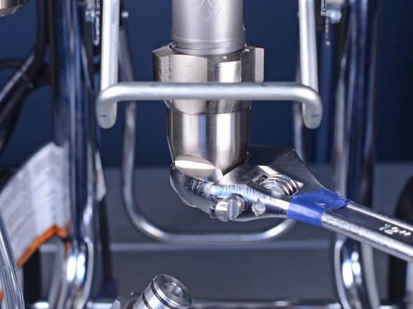
Use an adjustable wrench to loosen the intake valve on the pump.
-
-
-
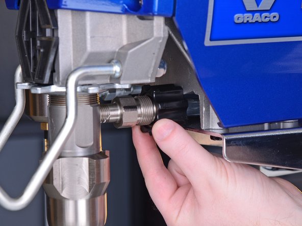
Employ your fingers to unscrew and loosen the connector securing the hose to the pump.
-
Once unscrewed, push the connector back to reveal the hose connexion.
-
-
-
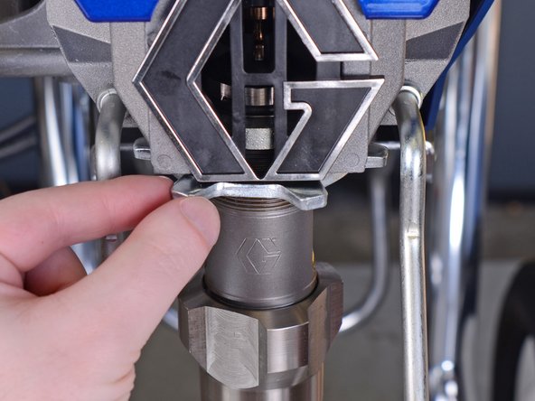
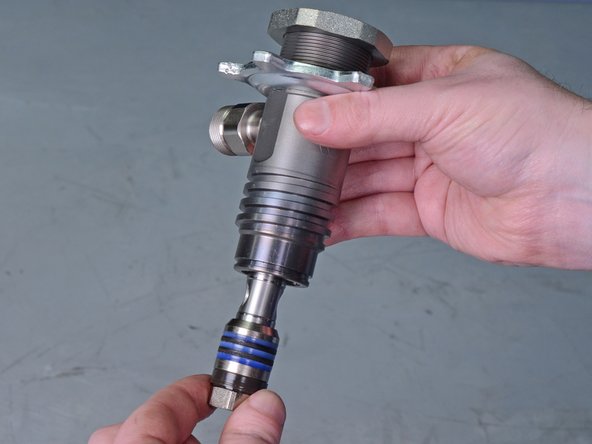
Apply your fingers to unscrew and loosen the jam nut securing the pump to the pigment sprayer.
-
-
-
Lift up the pump rod encompass to reveal the pump'south connection to the paint sprayer.
-
-
-
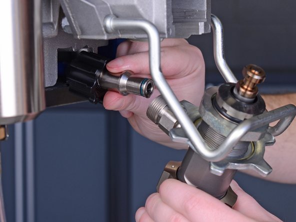
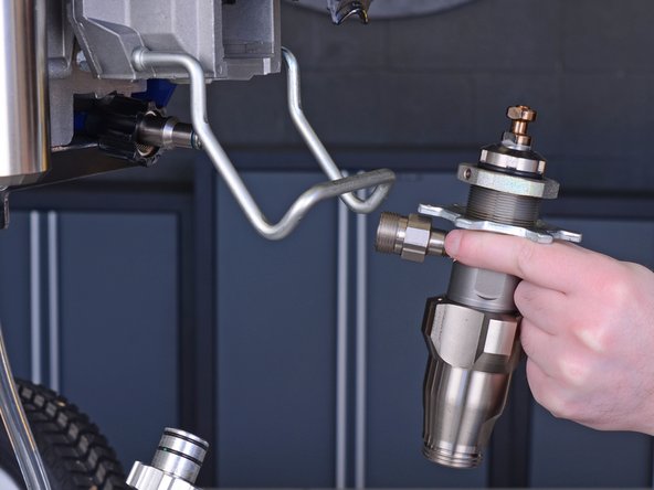
Pull the pump directly out of the drive housing.
-
-
-
Pull the rear pump hose straight off of the pump.
-
Remove the pump from the pigment sprayer.
-
-
-
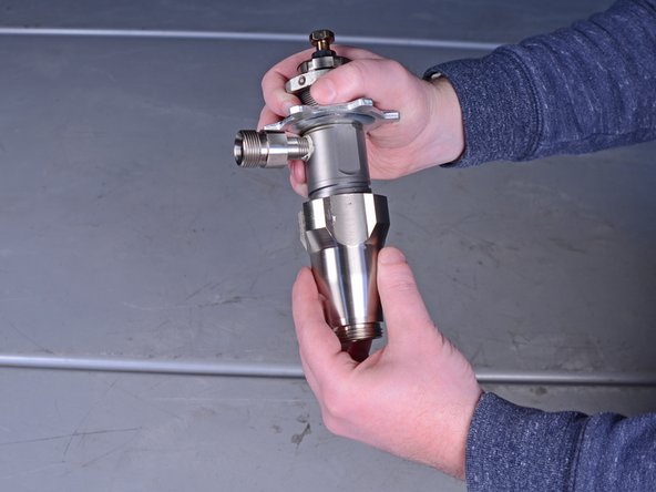
Unscrew and remove the intake valve from the pump cylinder.
-
-
-
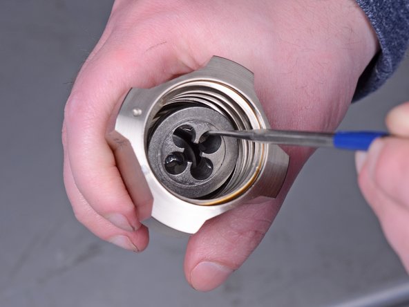
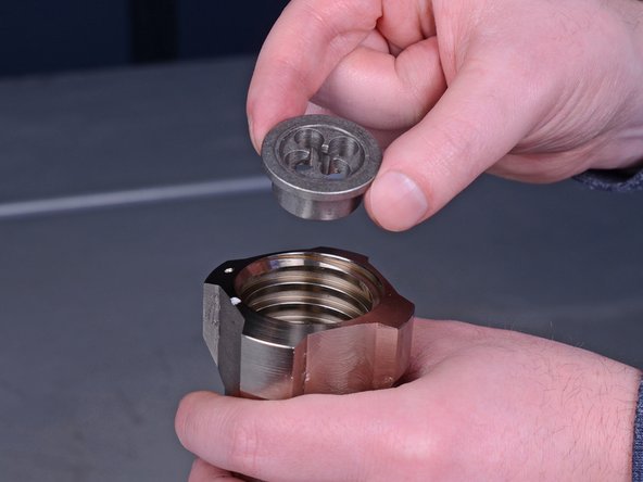
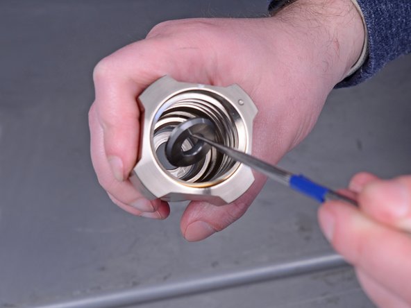
Utilise a pick tool to remove the metal brawl seat from the lesser of the intake valve.
-
-
-
Tip the intake valve upside downwardly to remove the inlet ball.
-
-
-
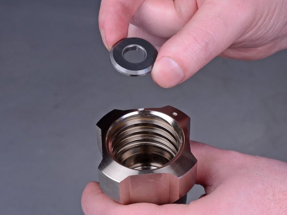
Utilize a selection tool to remove the brawl seat washer from the bottom of the intake valve.
-
-
-
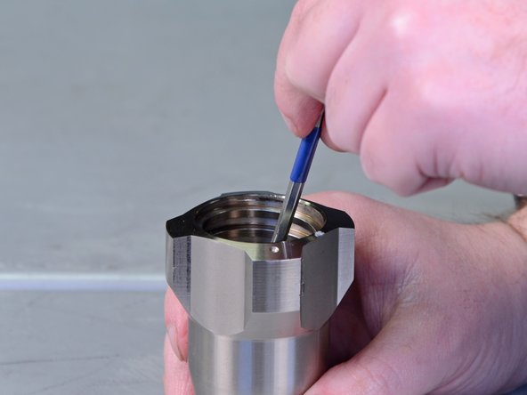
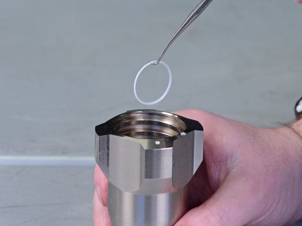
Apply a pick tool to remove the thin white O-ring at the bottom of the intake valve.
-
-
-
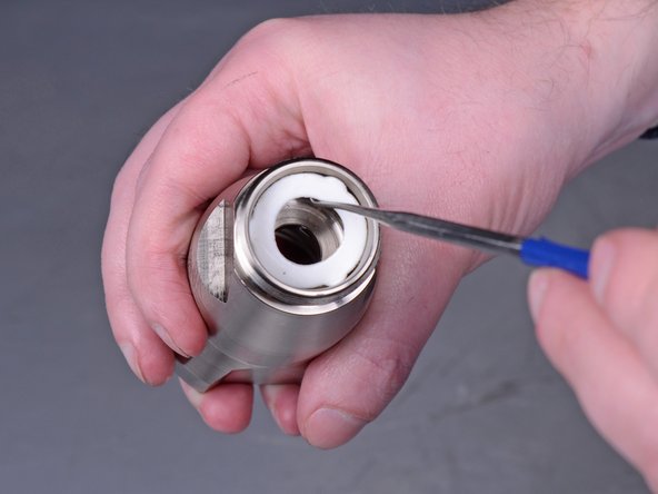
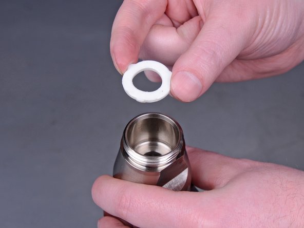
Turn the intake valve upside downwards and use a pick tool to remove the white gasket.
-
-
-
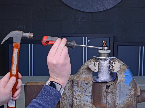
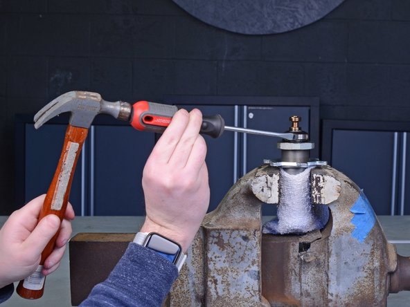
Identify the pump cylinder into a vise.
-
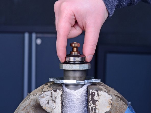
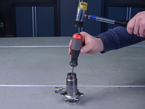
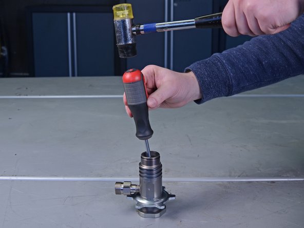
Use a flathead screwdriver and mallet to unscrew and loosen the superlative jam nut.
-
-
-
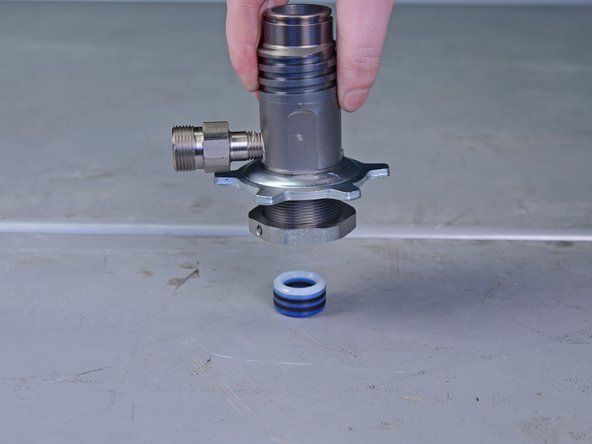
Keep unscrewing the top jam nut with your fingers to remove it.
-
-
-
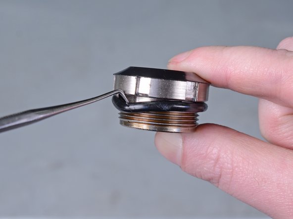
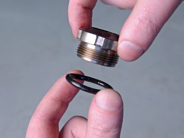
Use a pick tool to remove the black O-ring from the top jam nut.
-
-
-
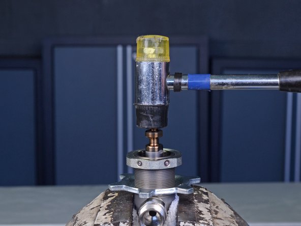
With the pump cylinder withal in the vise, use a mallet to gently tap down on the top of the piston rod to loosen it from the pump cylinder.
-
-
-
Remove the pump cylinder from the vise and pull the bottom of the piston rod completely out of the pump cylinder to remove it.
-
-
-
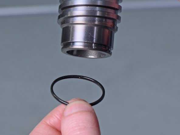
Utilise a pick tool to remove the black O-ring from the bottom of the pump cylinder.
-
-
-
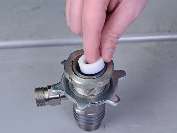
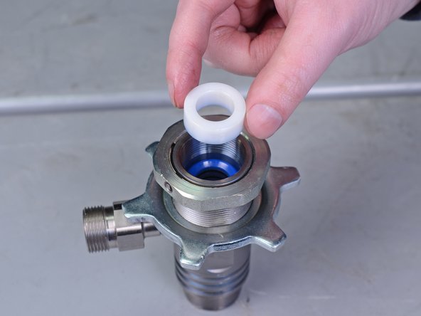
Use your fingers to grab and remove the white plastic gland from the top of the pump cylinder.
-
-
-
Flip the pump cylinder upside downwardly and use a flathead screwdriver and mallet to gently tap the throat packing O-rings, loosening them from the cylinder.
-
-
-
Lift upward the pump cylinder to remove the pharynx packing O-rings.
-
-
-
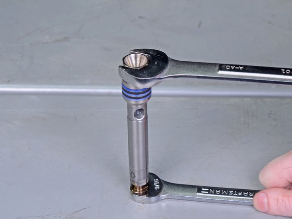
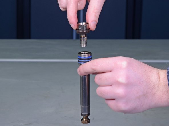
Utilise a 3/4" wrench to remove the piston valve bolt from the piston rod.
-
Remove the piston valve bolt from the piston rod.
-
-
-
Remove the wiper bushing from the piston valve bolt.
-
-
-
Use your fingers to remove the piston packing O-rings from the bottom of the piston rod.
-
-
-
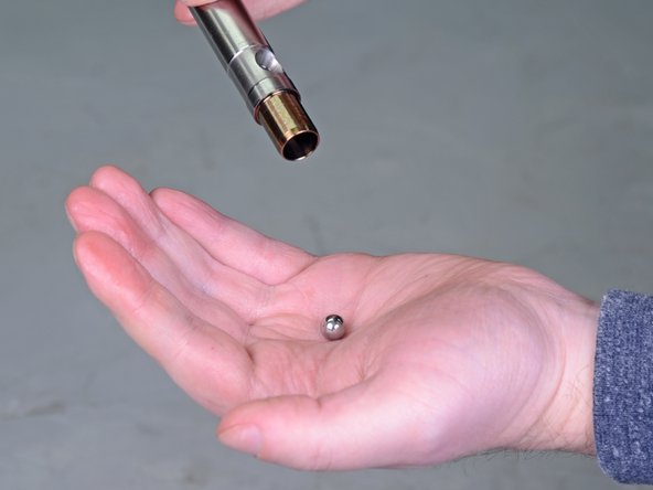
Tip the bottom of the piston rod over to remove the piston ball.
-


Conclusion
To reassemble your device, follow these instructions in opposite order.
Embed this guide
Choose a size and re-create the code beneath to embed this guide equally a minor widget on your site / forum.
Preview
Source: https://www.ifixit.com/Guide/Graco+Paint+Sprayers+17C325+2015+Pump+Rebuild/130026
0 Response to "How To Repair Graco Airless Pump"
Post a Comment